Executive Summary:
A Two-Port Network Analyzer (HP
8714B) is used to quantify Input Return Loss, Input Impedance and Common
Mode Impedance in stock and sample replacement current baluns in the BT1500A.
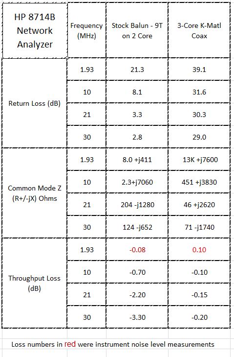
The stock BT1500 Balun is 9 turns of a two wire parallel transmission line on a two-core stack of unknown ferrite material. The replacement balun is 13 turns of RG-400 on a three-core stack of Amidon FT-240-K material.
The BT1500A input balun in SN 26387 has been observed to be comparatively poorer in Input Return Loss (RL) and lower in Common Mode Impedance than the replacement balun. The new balun is considerably higher reactance, higher Common Mode impedance and a much better RL.
The stock balun did not fail in circuit, even under high power conditions.
Detail Discussion:
Common Mode Impedance is a parameter
of concern for effective current baluns. Current baluns are often used to
decouple RF common mode currents that would form on the outside shield of
a coaxial feedline. A current balun is also frequently used provide a connection
to a two wire transmission line from a unbalanced coaxial transmission line.
A current balun is used on the input of the Palstar BT1500A Balanced Coupler
to present an unbalanced transmission line to the dual L-topology matching
network for use with a balanced transmission line.
The stock BT1500A balun (at least as found in S/N 26387) is made with parallel wound high voltage wire, 9 turns on a two-core stack of unknown characteristics ferrite. As a transmission line, it is likely somewhat higher impedance than 50 Ohms but it is speculated that in the application the designers were not so much concerned with building a near perfect 50 Ohm choke as they were with presenting a high impedance as possible to common mode currents, and ideally a near balanced current into a load at all frequencies of interest.
The inductance of the choke if prepared correctly should present a high impedance at all frequencies of interest, with no spurious resonances that would complicate the network transformation, or disturb the phase balance between the two sections of the network.
The non-50 Ohm nature of the stock balun winding transmission line characteristic impedance, is likely matched to the external transmission line as part of the network transformation.
Discussions in the literature
suggest that a desired 1000 Ohms of balun reactance is a good target, and
higher is generally better, and achievable. 1000 Ohms at 1.8 MHz is about
88 uH. High Z across all frequencies and no series resonances is hard to
achieve, and some very good commercial examples are made qualified by band
and measurements.
The primary interest of the group
is on lower frequencies, and specifically performance at 160M. The construction
of the balun was biased towards better common mode performance at 160, though
the evidence is that the new balun is perfectly usable from 1.8 to 30 MHz.
Calibration was done first with a good Open, Short and 50 Ohm High RL Load from 1 to 50 MHz. There is a valid argument that the analyzer is designed to work into a 50 Ohm transmission line, and the parallel wound transmission line balun is likely higher than 50 Ohms.
The absolute accuracy of any
of the results is a question, though for comparison purposes the trends
and gross magnitude of the differences are useful. Note that the resistive
portion of the common mode measurment of the new balun seems to go through
an inflection point that is unrealistically high in comparison to other
frequencies. A view of the graphical results on the smith chart presentation
shows the impedance is high and clustered at the far right, out of range
of measurment. The result indicated numerically would jitter about an extremely
high number. The trend is important, even if it is difficult to say the
exact value. This is a limit of the instrumentation and technique.
The modifications to the BT1500A were captured in a way that should allow improvised duplication.
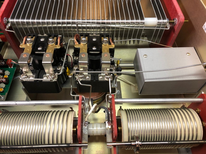
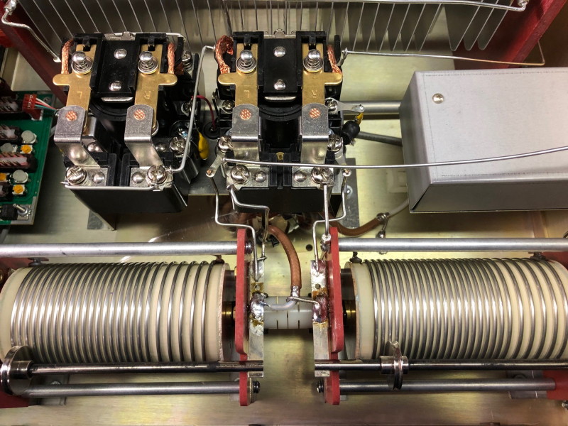
Figure 1. View of the Stock BT1500A Prior to Removal of the Stock Balun
Figure 1 shows an inside view of the BT1500A prior to modification. It is recommended that an image like this is available to the modifier so that there is a reference view when complete. Some serial numbers had differing version of the 1:1 Balun so the view may be slightly different, though the connection points should be identical. The screws that hold the network connection wires were removed and set aside, to allow access for the lifting of the bracket that holds the relays. The stock balun wires can then be unsoldered from the input and output side.
The cover over the directional coupler is lifted off to allow access to the soldered connection at the rear, which is the output of the coupler and the input to the balun. The other input wire of the balun is soldered to a ground lug under the relay plate.
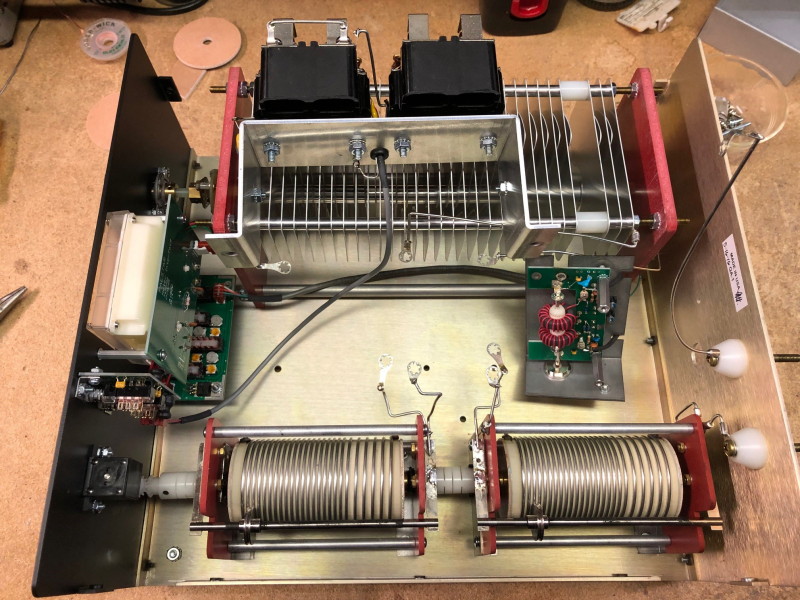
Figure 2. View of BT1500A With Relays Set Aside for Access
Figure 2 shows the view with the relay bracket pulled aside, the stock balun removed for access to the space for the new balun.
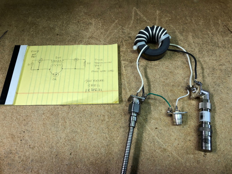
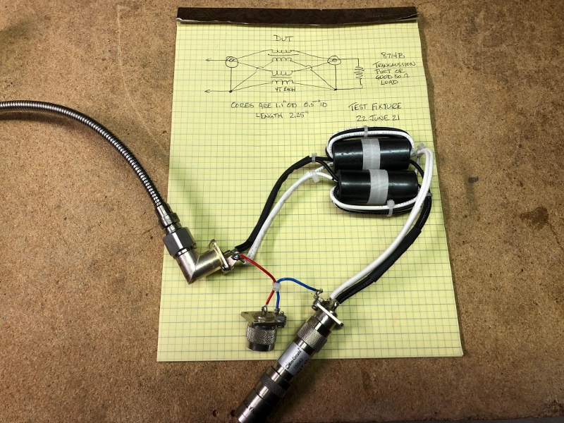
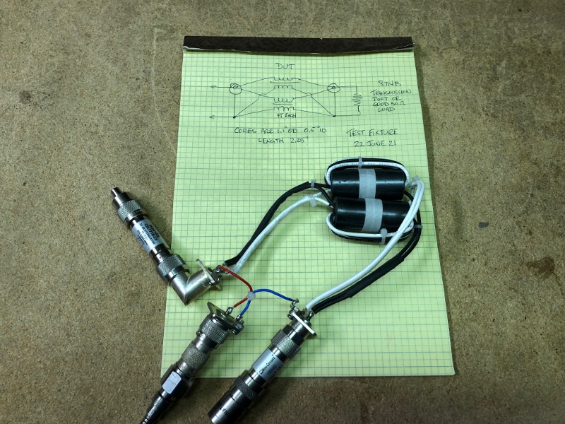
Figure 3. Setup For Return Loss, Input Impedance and Throughput Loss - Stock Balun
Figure 3 shows the setup for measurement of Input Return Loss, Input Impedance and Throughput Loss on the stock balun. The Analyzer reflected port was connected to the input of the balun, and the output was initially terminated in a known 50 Ohm load.
For Throughput Loss, the 50 Ohm load was replaced with the Transmission Port on the analyzer.
The Balun consists of 9 Turns of parallel wire transmission line on two stacked cores. The core material is unknown.
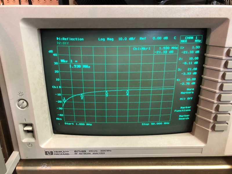
Figure 4. Input Return Loss of Stock Balun
Figure 4 shows the display on the analyzer as set to observe Input Return Loss (RL) vs frequency on the Stock Balun, with markers at four frequencies of interest. RL appears good at the low end of the spectrum with progressive deterioration at higher frequencies.
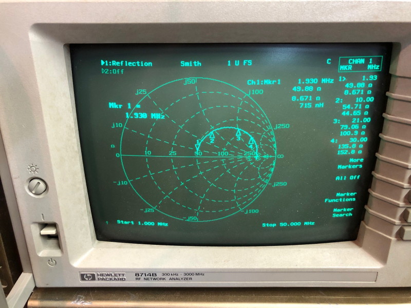
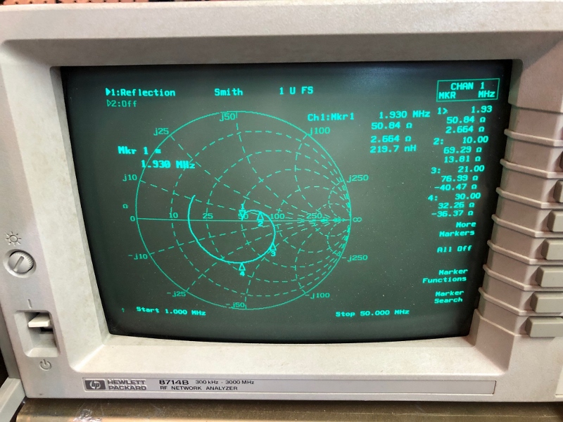
Figure 5. Input Impedance of Stock Balun
Figure 5 shows the same connection with the analyzer set to show Impedance on a Smith Chart presentation. Markers indicate the observed Impedance (R +/- jX). The balun appears inductive through the operating region. Loss through the stock balun was not measurred, as it was speculated that the 50 Ohm terminations of the instrument would somewhat mis-terminate the balun yielding a possibly higher than in-circuit loss.
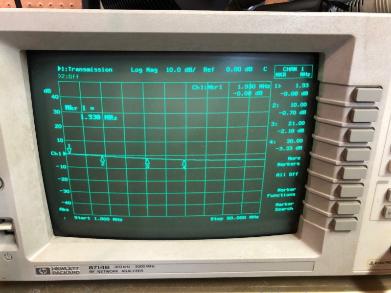
Figure 6. Throughput Loss on Stock Balun
Figure 6 shows the throughput loss on the Stock Balun. Note that the results show the loss with the stock balun terminated in a 50 Ohm system. The characteristic impedance of the stock balun is likely not 50 Ohms, and so some of the loss can be attributed to mismatch losses.
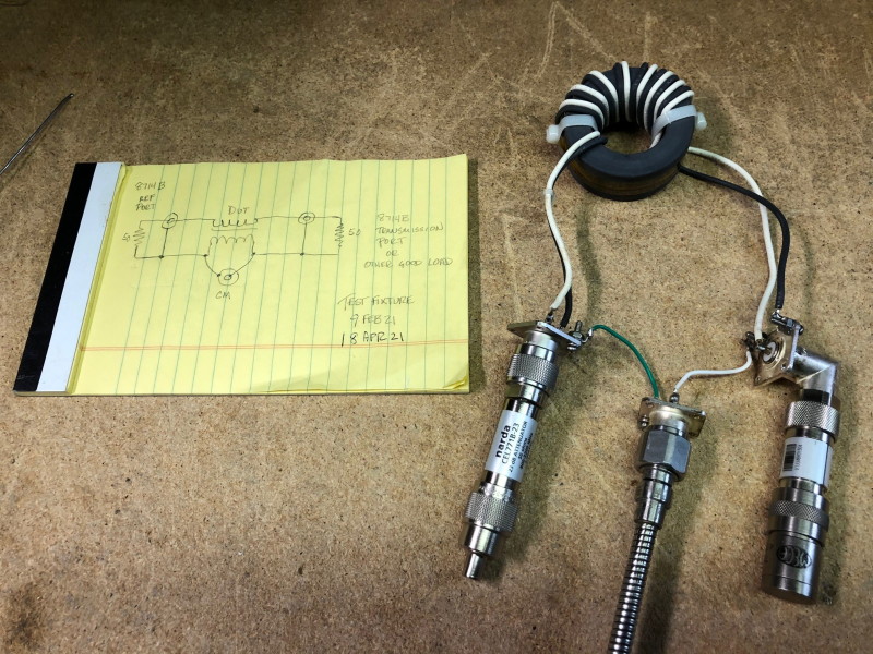
Figure 7. Setup for Common Mode Impedance on Stock Balun
Figure 7 shows the setup to indicate Common Mode Impedance using the Reflected Port of the analyzer.
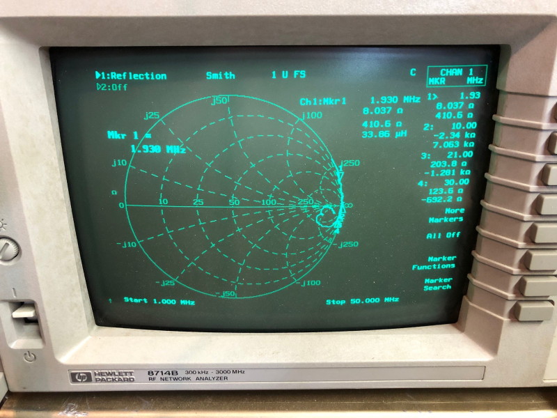
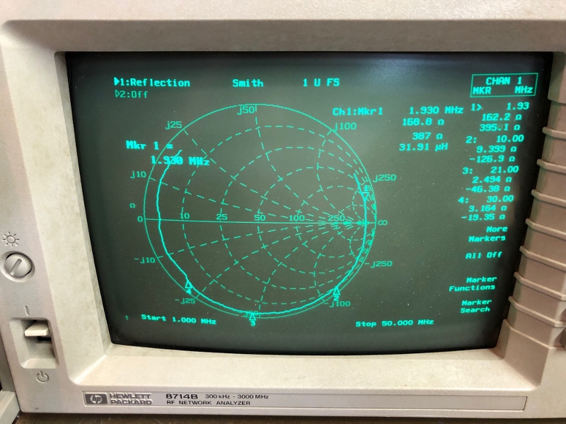
Figure 8. Common Mode Impedance Observed on Stock Balun
Figure 8 shows the display of the analyzer, indicating the Common Mode Impedance trends with the input and output of the balun terminated in 50 Ohms. Note the value observed at 1.93 MHz of approximately 8.0 +j411 Ohms which ideally would be in excess of 1K Ohms. It is important to note, this balun works well in circuit, even at high power (1500 watts) so questionable measurements may not indicate failure of the balun to work.
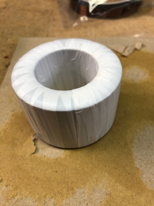
Figure 9. Construction of the Replacement Balun
Figure 9 shows the three cores of FT-240-K material obtained from Amidon.
K type material is used primarilly in transmission line transformers fro 1 MHz to 50 MHz.
A very small dot of glue was used at cardnal points on the common faces of the cores and they were stacked. When dried, the stack was wound with a layer of PTFE tape.
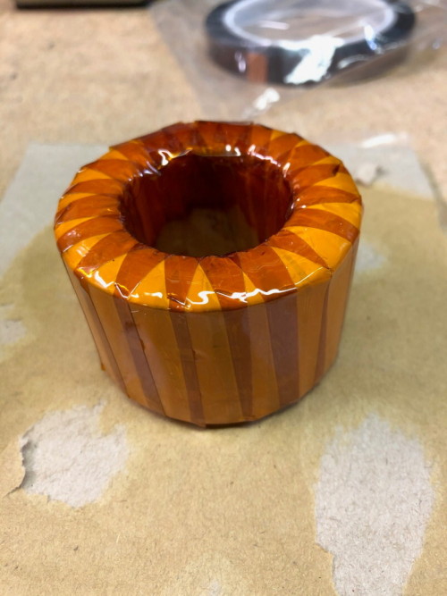
Figure 10. Three Core Stack Wound With Kapton Tape
Figure 10 shows the three core stack wound with Kapton tape prior to winding the transmission line on the cores.
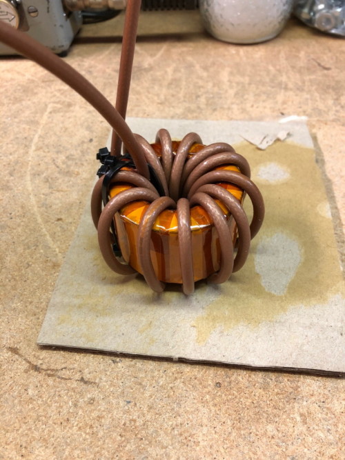
Figure 11. Three Core Stack Wound With RG-400
Figure 11 shows the three core
stack prepared and wound with 13 turns of RG-400 coax. This is the ideal
material to use as it has a PTFE dielectric for a high temperature rating,
easy to solder without distorting the dielectric and is 50 Ohms characteristic
impedance.
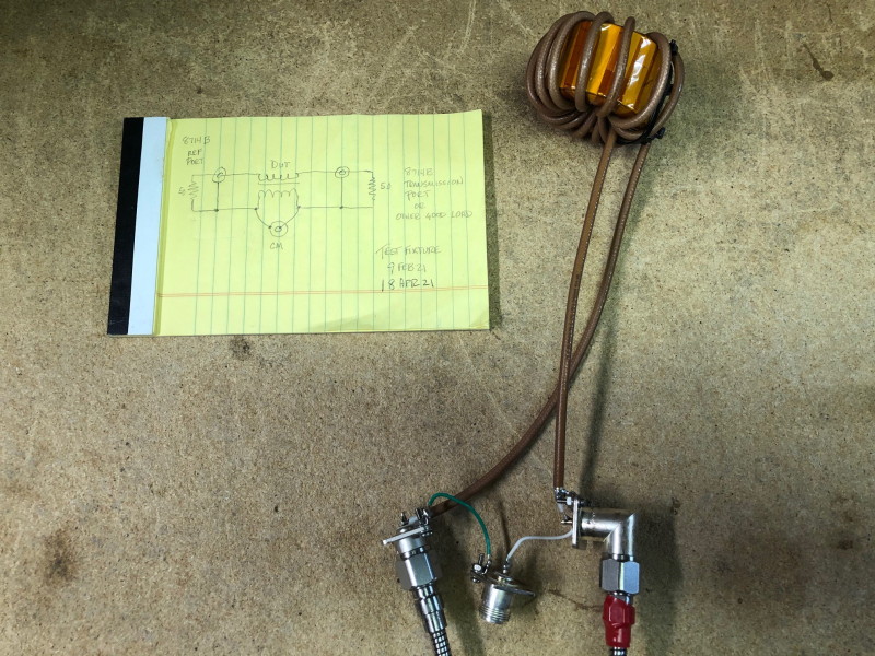
Figure 12. Input Return Loss, Input Impedance and Throughput Loss Measurment Setup on New Balun
Figure 12 shows the setup for measurment of the Return Loss (RL), Input Impedance and Throughput Loss of the new balun.
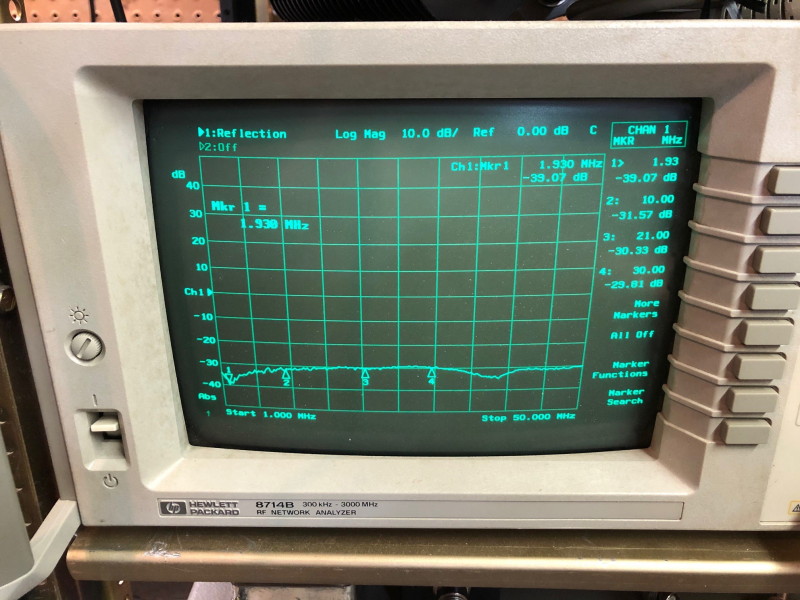
Figure 13. Input Return Loss of the 3-Core 13-Turn K-Type Balun
Figure 13 shows the Input RL for the new balun. This is considerably better than the stock balun, and measurable with reasonable accuracy in a 50 Ohm test system.
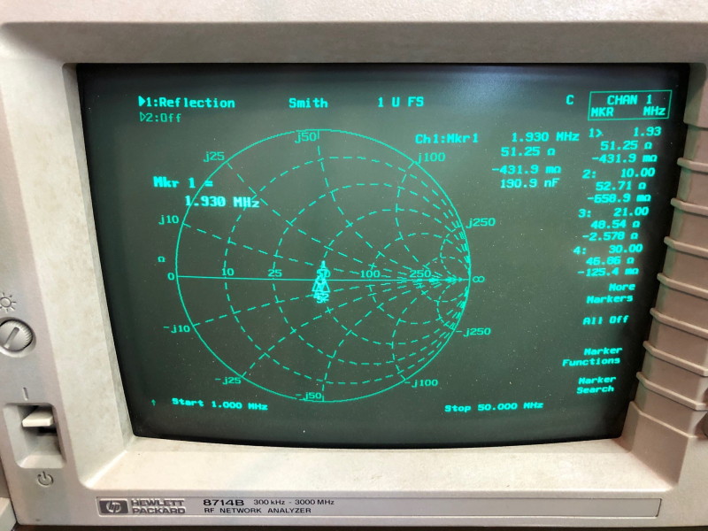
Figure 14. Input Impedance of the 3-Core 13-Turn K-Type Balun
Figure 14 shows the input impedance of the new balun. Note that the cluster of points is more consistantly near 50 Ohms across the usable frequency range.
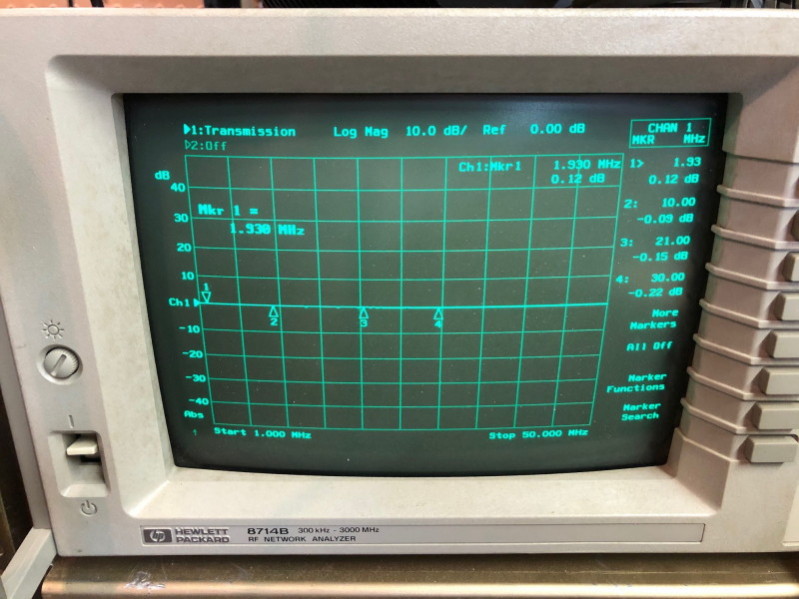
Figure 15. Throughput Loss of the 3-Core 13-Turn K-Type Balun
Figure 15 shows the throughput loss measured on the new balun. Measurement of a positive value at 1.93 MHz is due to results being at the noise level of the instrument.
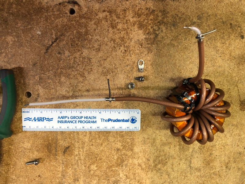
Figure 16. New Balun Prepared Ends
The ends of the new balun were prepared as shown in Figure 16 for ease of dress within the BT1500A. Lengths are approximate. .
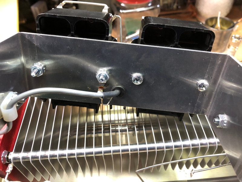
Figure 17. Reverse Screw Heads on the Relay and Cable Dress
Figure 17 shows the screws holding the right side relay reversed top-to-bottom out of concern for height space available for the new balun. The cable was also dressed away from the anticipated location of the new balun using an existing hole and a small plastic clip.
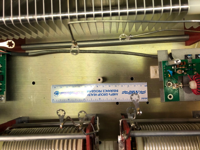
Figure 18. New Hole in Chassis
Figure 18 shows the placement of a new hole in the chassis sized to pass a #6 bolt 3/8" long for a ground lug, that will terminate the shield of the input coax of the new balun. The location is not critical but should be close to and below the directional coupler output attachment point. Note also that a 1" long by 0.25 diameter ceramic post has been added in the original location for the screw bolt that attached the original balun. This post is to trap the new balun from lateral movement underneath the relay bracket.
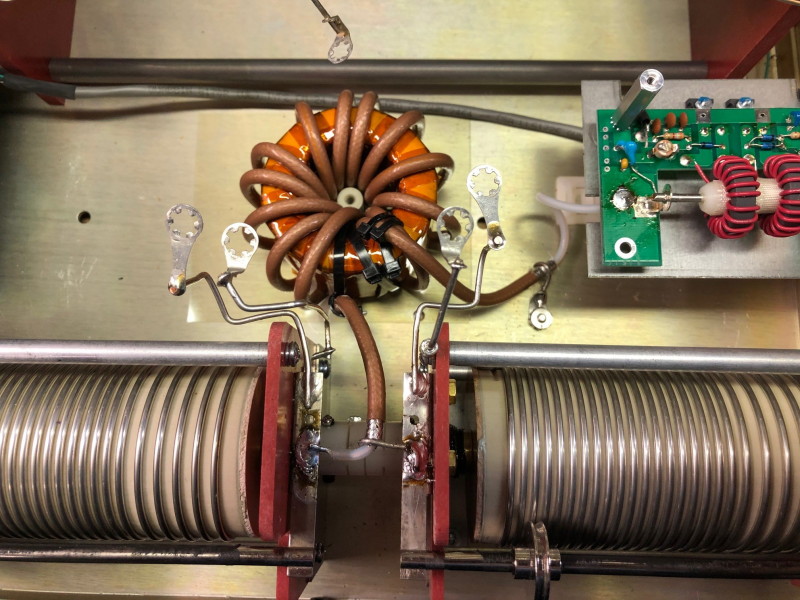
Figure 19. Placement of the New Balun
Figure 19 shows the placement of the new balun in the position under the relay bracket. A sheet of 1 mil "ULTIM" high voltge insulation was placed beneath the balun. Another sheet was placed over the top of the balun. No hardware was used to otherwise captivate the balun. The coax was soldered in place.
.
Figure 20. View of Relay Bracket in Place
Figure 20 shows the relay bracket and relays in place with all lines reconnected.
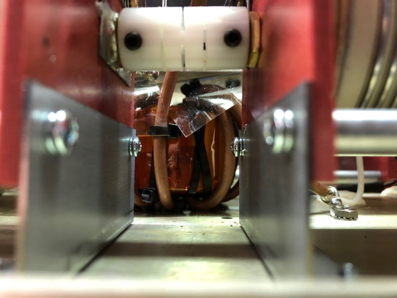
Figure 21. View of New Balun From Side
Figure 21 shows available clearance above the new balun in place.
APPENDIX
Some additional data was taken on the two-core balun in some versions of the BT-1500 original balun. The setup and results images are as follows:
Appendix Figure 1. Alt Stock Balun Input Z Measurement Setup
Appendix Figure 2. Alt Stock Balun Input Z Results
Appendix Figure 3. Alt Stock Balun Common Mode Measurement Setup
Appendix Figure 4. Alt Stock Balun Common Mode Results